
What Do The Lights Mean On An Arduino? (Full Light Guide)
For most of my time spent working with an Arduino, I’ve ignored the light show that took place on it. I soon came to realize that some devices use light as a way of communicating and reporting problems (like a Raspberry Pi).
Consequently, to prepare for any potential issues I may encounter in the future, I sought to answer the question that Arduino users may wonder: “What do the lights mean on Arduino?”
There are 3 main types of LEDs (or Light-Emitting Diodes) on your Arduino: power LED, pin 13 LED, and serial LEDs. The first type will let you know if your Arduino is receiving power. The second type is connected directly to pin 13 on your Arduino board, which means you can control it. The last type consists of 2 LEDS (RX and TX) and they’re used for serial communication.
If you want to learn more about these LEDs, how to read their patterns, and how to control some, then the rest of my guide will cover all that and more.
1. Power LED
This LED is located next to the “ON” text on your Arduino board. It indicates whether or not your Arduino is receiving enough power.
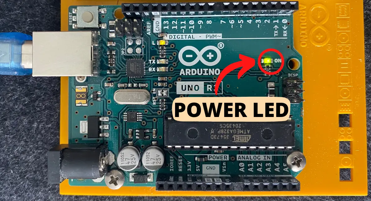
It will glow green if the appropriate power is received and turn off if it doesn’t receive power.
If you have your Arduino plugged in and this LED doesn’t emit a light, that indicates you have a short circuit, your board isn’t receiving enough power, or your board is drawing too much power from the 5V pin.
Short circuit occurs when there is a new path of least resistance the electrons in the circuit can take. This diverts the power your Arduino receives and causes it to not turn on. You should check your breadboard and use a multimeter to make sure this isn’t happening.
Another reason why the ON LED might not turn on is because your board isn’t receiving enough power. Here are some of the potential sources for this issue:
- Not enough voltage through Vin pin.
- The minimum voltage you can apply to your Arduino is 6V. Anything less than that would result in your Arduino not functioning properly and auto-resetting. Still, the 6V may not be enough when it’s being converted through the voltage regulator
- Solution: I’d recommend you to supply your Arduino with at least 9V through the Vin pin.
- Your computer’s USB port is worn.
- You can tell it’s worn out if the port looks dirty, rusted, or dusty.
- Solution: Go buy a new computer or a refurbished one. It will be well worth the investment for both your Arduino adventure and your future web surfing exploits.
- Your USB cable is defective.
- To make sure it is your USB cable that’s damaged, connect your Arduino to a different USB cord that you know works for sure.
- Solution: If the cable is damaged, just buy a new USB cable as it is relatively cheap. For example, it costs around $7 on Amazon.
- Power adapter
- If you’re powering your Arduino through a power adapter, you need to either make sure the outlet it’s plugged into works or that the power adapter is meeting the minimum voltage requirement.
- Solution: Switch to an outlet you know works or buy a power adapter compatible with an Arduino board
A third reason is that you’re inputting too much power through the 5V pin (if you’re powering it that way). The Arduino will shut down to protect itself from overheating and frying due to the thermal protection circuit built into the voltage regulator.
Consequently, you should switch from the 5V pin to the Vin (which stands for ‘Voltage In’) pin since it can tamp down the power through its voltage regulator. Otherwise, you’ll need to input 5V through the 5V pin (as the name suggests).
2. Pin 13 LED
This LED is located next to the “L” text on your Arduino board. It indicates the state of your 13 pin, which could either be HIGH or LOW.
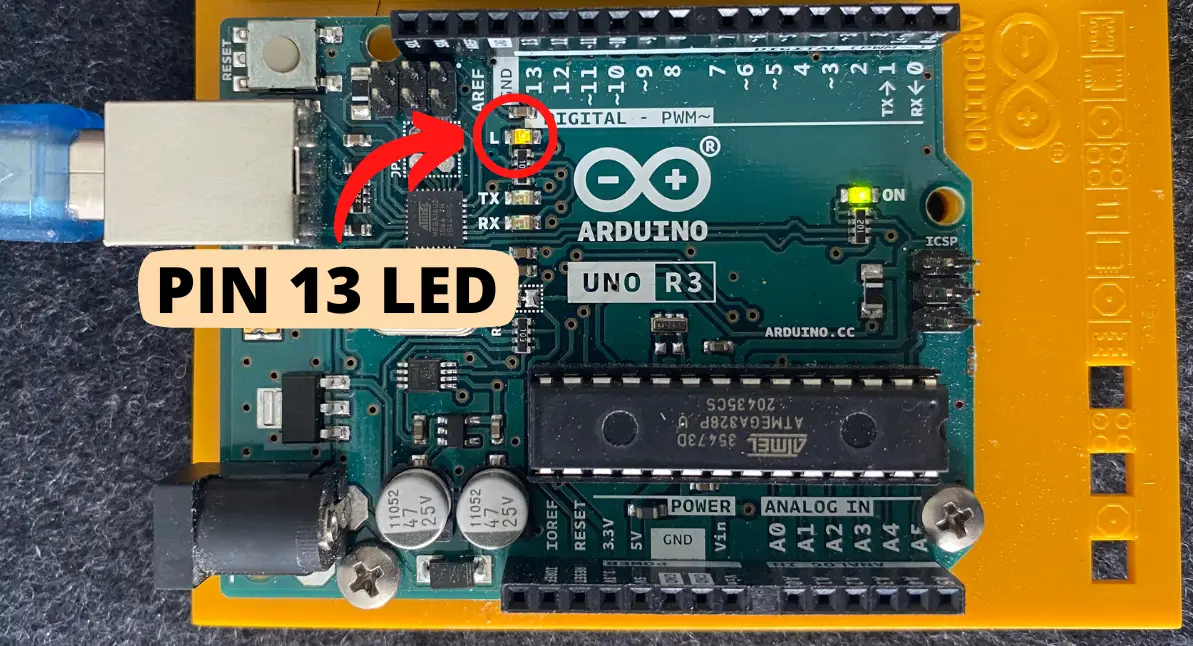
If the state of pin 13 is HIGH, then the LED will glow yellow. If the state is LOW, then the light will turn off.
When you first power on your Arduino, the L LED will blink on and off by default to show you that it’s working. That’s because it has a software preprogrammed on it when it comes straight out of the factory.
Consequently, you can program and control this LED using the Blink test, which is a good test all beginners should implement to see if their Arduino is functional.
This test is a precoded example in the Arduino IDE (Integrated Development Environment). You can find it by following these steps:
- Open the Arduino IDE
- Click File
- Click Examples
- 01.Basics
- Blink
Alternatively, you can just copy and paste this code (which is directly from the Arduino IDE) into the IDE and upload it to your Arduino:
/*
  Blink

  Turns an LED on for one second, then off for one second, repeatedly.

  Most Arduinos have an on-board LED you can control. On the UNO, MEGA and ZERO
  it is attached to digital pin 13, on MKR1000 on pin 6. LED_BUILTIN is set to
  the correct LED pin independent of which board is used.
  If you want to know what pin the on-board LED is connected to on your Arduino
  model, check the Technical Specs of your board at:
  https://www.arduino.cc/en/Main/Products

  modified 8 May 2014
  by Scott Fitzgerald
  modified 2 Sep 2016
  by Arturo Guadalupi
  modified 8 Sep 2016
  by Colby Newman

  This example code is in the public domain.

  https://www.arduino.cc/en/Tutorial/BuiltInExamples/Blink
*/

// the setup function runs once when you press reset or power the board
void setup() {
  // initialize digital pin LED_BUILTIN as an output.
  pinMode(LED_BUILTIN, OUTPUT);
}

// the loop function runs over and over again forever
void loop() {
  digitalWrite(LED_BUILTIN, HIGH);   // turn the LED on (HIGH is the voltage level)
  delay(1000);                       // wait for a second
  digitalWrite(LED_BUILTIN, LOW);    // turn the LED off by making the voltage LOW
  delay(1000);                       // wait for a second
}
By default, this test will blink the Arduino’s L LED in 1 second intervals. This means that the light will turn on for 1 second and turn off for 1 second repeatedly.
If you want to change the speed of the light turning on and off, you can change the number inside the delay function (which happens to be 1000). The number represents the time in milliseconds, which means if you want it to last 3 seconds, for example, then you’d replace 1000 with 3000!
You can also light up the L LED with the default, basic sketch you’d see when you open up Arduino IDE. I’m talking about the program that only includes void setup() and void loop() functions that have nothing in them.
Note that if pin 13 is set to input (for example: pinMode(13, INPUT)) and it’s not connected to anything, then it’s susceptible to high-impedance, which means it the L LED will light up.
This happens because the L LED is operated by the op-amp (operational amplifier), which is named U5B. It may detect random voltage, thus activating the LED.
This op-amp is only found on the Arduino Uno Rev 3 board and not for the previous generations.
3. Serial LEDs
There are 2 LEDs used for serial communication between your computer and your Arduino. One is located next to the “RX” lettering on the board and the other is located next to the “TX” lettering.
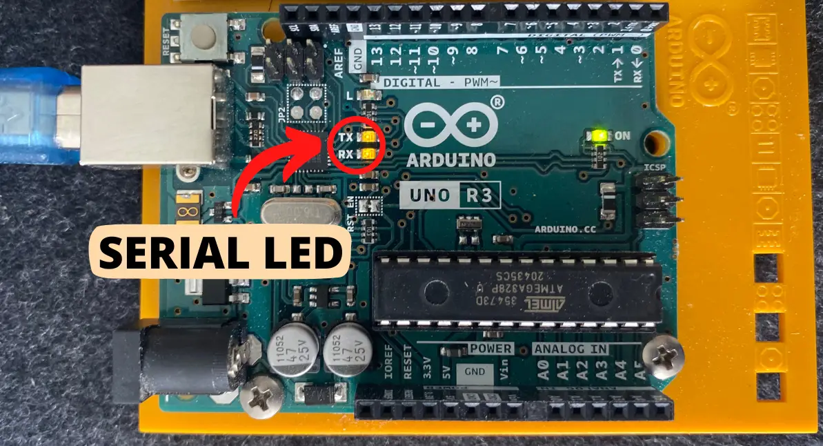
These components are LEDs that emits an orange or yellow color. They only operate when the Arduino board is connected through USB. When they light up, you’ll know that serial communication is happening.
When the RX (Receive) LED lights up, that means the Arduino is receiving data from your computer.
When the TX (Transmit) LED lights up, that means the Arduino is sending data to either your laptop or other electrical devices (like sensors). The TX LED is connected to the USART transmitter pin.
The TX and RX pins should both light up when you hit the upload button on your Arduino IDE.
They’re both used for a serial communication called USART (Universal Synchronous/Asynchronous Receiver/Transmitter). You can use this to communicate with any other device that has USART protocol, but you’ll need to make sure that the baud rate (which is the bits per second) are identical in your code and in the serial monitor.
The necessary functions you’ll need to communicate between your computer and Arduino are:
- Serial.begin(baud_rate) – You’d replace the “baud_rate” (which is number of times in which the signal changes per second) with a number like 9600. You’d put this in the void setup() function
- Serial.write(data) – You’d replace “data” with some text that you’d like to send to the Arduino
- Serial.available() – This lets you check to see if the board sent you any information
You should always leave your RX and TX pins open whenever you are uploading code to your Arduino. If they are connected to something, then the Arduino might not be able to program properly or the component connected to these pins would get corrupted (although the latter is less likely to occur).
Note: I talk a lot more about TX and RX LEDs and how you can use them for serial communications in my debugging guide. You need to check it out if you want to learn more about concepts like baud rate or USART!
Summary – tl;dr (Too Long; Didn’t Read)
Here are the key takeaway points you should keep in mind after reading this article:
- There are 4 main LEDs built into your Arduino board:
- ON LED
- This tells you the power status of your board
- L LED
- This tells you the status of pin 13
- RX LED
- Used for serial communication and lets you know if it received any information
- TX LED
- Also used for serial communication and lets you know if it is transmitting any information
- ON LED
In the end, I hope you were de-light-ed to learn as much about the built-in LEDs on the Arduino as I was.