Top 15 Equipment You’ll Need When Starting Arduino
When I started as a beginner, I tried figuring out what I needed to start working with my Arduino. I researched heavily, and I realized that I could just go with a starter kit and save myself the trouble of buying each component separately. Still, some of you might not want to go that route, so you may be wondering:
“What equipment do you need before starting Arduino?”
Besides the Arduino and a computer, you should have a USB cable, jumper wires, a breadboard, resistors, an LED, and a switch for basic projects. For complex projects, you should also get a potentiometer, servomotor, temperature sensor, DC motor, phototransistor, transistor, diode, tilt sensor, and piezo.
This is not an exhaustive list, and there are other components that are more suited to your projects. Nevertheless, I will go into detail about these components for those who don’t what these components are or for those who just need a refresher.
Arduino and USB Cable
The Arduino is a microcontroller development board that uses an Atmel microcontroller (or to be more specific, the ATmega328P).
If you want to understand the difference between a microcontroller and an Arduino and which one is better, go check out my guide on Arduino and microcontrollers.
For many beginners, you would use a USB cable to connect your computer to the Arduino. This serves two purposes: it powers your Arduino, and your computer is now able to upload code to the Arduino (which gives it many functionalities).
An Arduino by itself isn’t impressive. It doesn’t have cool capabilities yet. It might be able to flash its own built-in LED light if you connect it to a power source, but it’s not very interesting after you play with it for 5 minutes.
That’s why you need to use other components and upload sketches to the Arduino board to create cool projects.
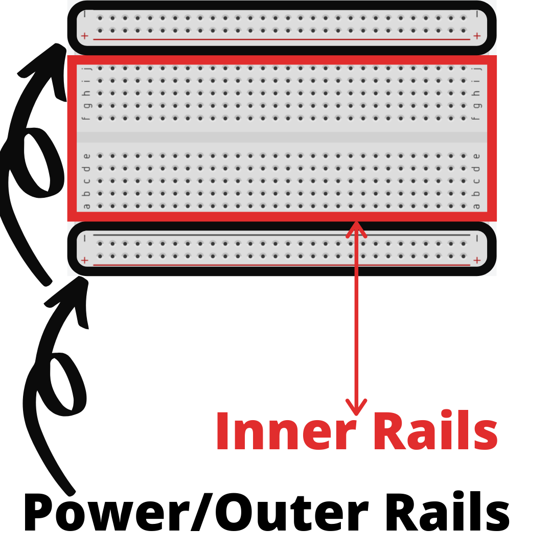
Breadboard
Let’s first talk about a breadboard. This is the meat of many projects for beginners because it allows them to be accustomed to building circuits without having to learn and use a technique called soldering.
What is soldering?
Soldering is basically melting a solder (or a metal alloy made of lead or tin) to the metal parts of electrical components to permanently fuse them together. This allows a permanent electrical connection to take place.
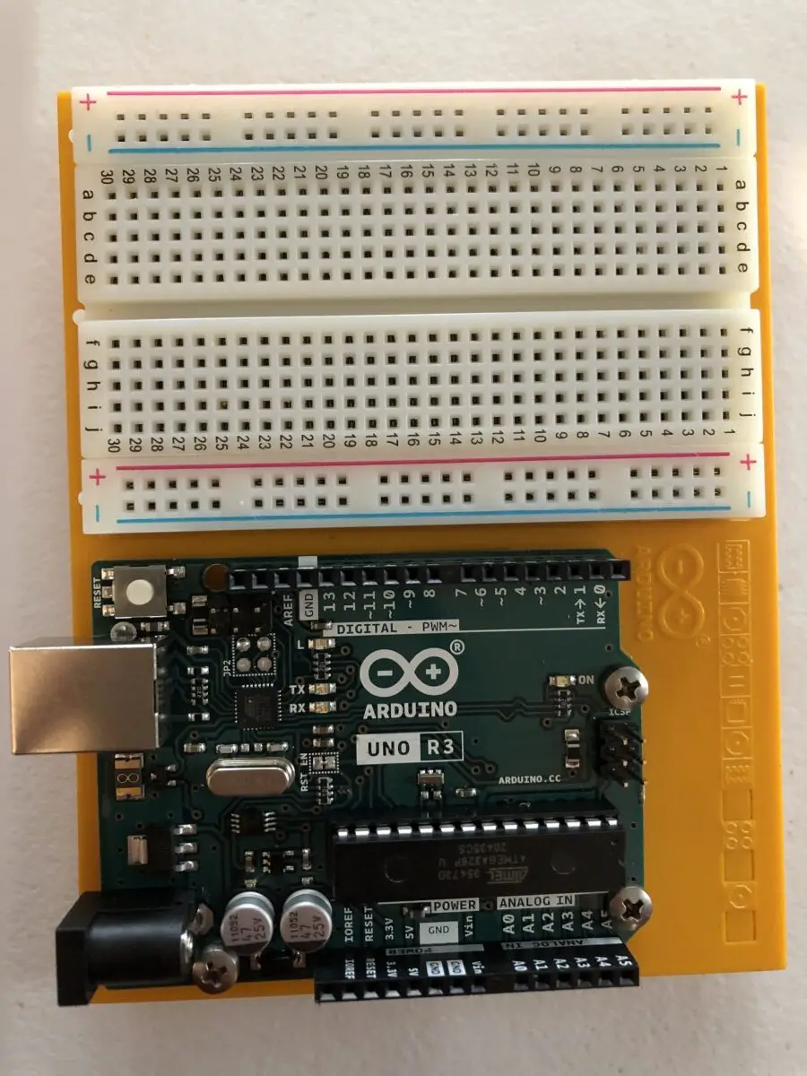
Underneath the exterior, breadboards have power rails, which are just long strips of metal wires. From the outside, you’d see it by finding the long line of holes enclosed by a blue and red line on the outermost area of the breadboard.
Then there are smaller strips of wire that run perpendicular to the previously mentioned long strips of wire. They are numbered from 1 to 30 the long way and numbered A to E and F to J the short way.
Typically, breadboards come with a sticky adhesive on the back for sticking onto surfaces.
From my personal experience, once you choose where to stick your breadboard, you must commit to it. I didn’t know this at first and tried to pull my breadboard apart from the surface it was stuck to. The adhesive is very strong and my breadboard almost broke apart despite my efforts to be careful with it.
Anyways, you’re supposed to stick leads (or the metal wire) of components into these holes (also referred to as sockets) to create a circuit.
Jumper Wires
Jumper wires are wires covered in different colored plastics, and they come in varying lengths. They have a connector pin on both ends, which allows them to be used in breadboard without the need for soldering.

These wires are used to make connections between components on your breadboard (such as a LED pin) or to connect to your Arduino.
Though they come in varying colors, they actually have no meaning. However, from my experience, you should color code them. Conventionally, you would assign red-colored wires to positive (power or where you’re receiving power form) and black-colored wires to negative (ground or where the current is leaving).
This is essential because if you don’t keep track of your wiring, you can screw up the circuit. As a result, this can either lead to short-circuiting or the project not running.
Short circuiting can cause an Arduino to fry. If you want to learn more about it and prevent it from happening to you and your Arduino in the future, go read my guide on preventing an Arduino from frying.
If you have wires that aren’t colored, are all the same colors, or are very close in color, I’d highly recommend you going out and buying some different colored nail polish. You need to paint half of them a certain color (perhaps red) and the other half a different color (perhaps black).
Just make sure to use visually distinctive, different colors. If they’re close in color, you might get them mixed up if you’re in a rush or you’re working in poor lighting conditions.
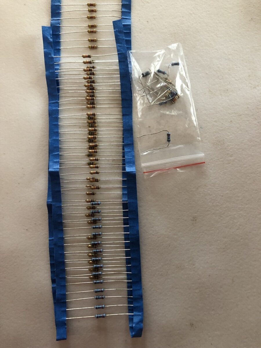
Resistors
Resistors are used to limit current or resist the flow of electricity, which changes the voltage and current. This is necessary to prevent certain components (like an LED) from taking too much current and getting damaged.
Let’s use an LED as an example. Say you used a design that made an LED blink, but you neglected to use a resistor. The LED would take in more current than it can handle, causing it to overheat, light up very brightly for a few seconds, and then burn out.
This means that the LED won’t work anymore because it’s damaged. Moreover, a lot of heat will be generated, and you may see the LED emitting smoke.
You can calculate the resistance you need by using Ohm’s Law. This law determines the relationship between the current (denoted with the symbol I), the voltage (denoted with V), and the resistance (denoted with R). It has a very simple equation that you should memorize when working with Arduino, which is: V = I * R.
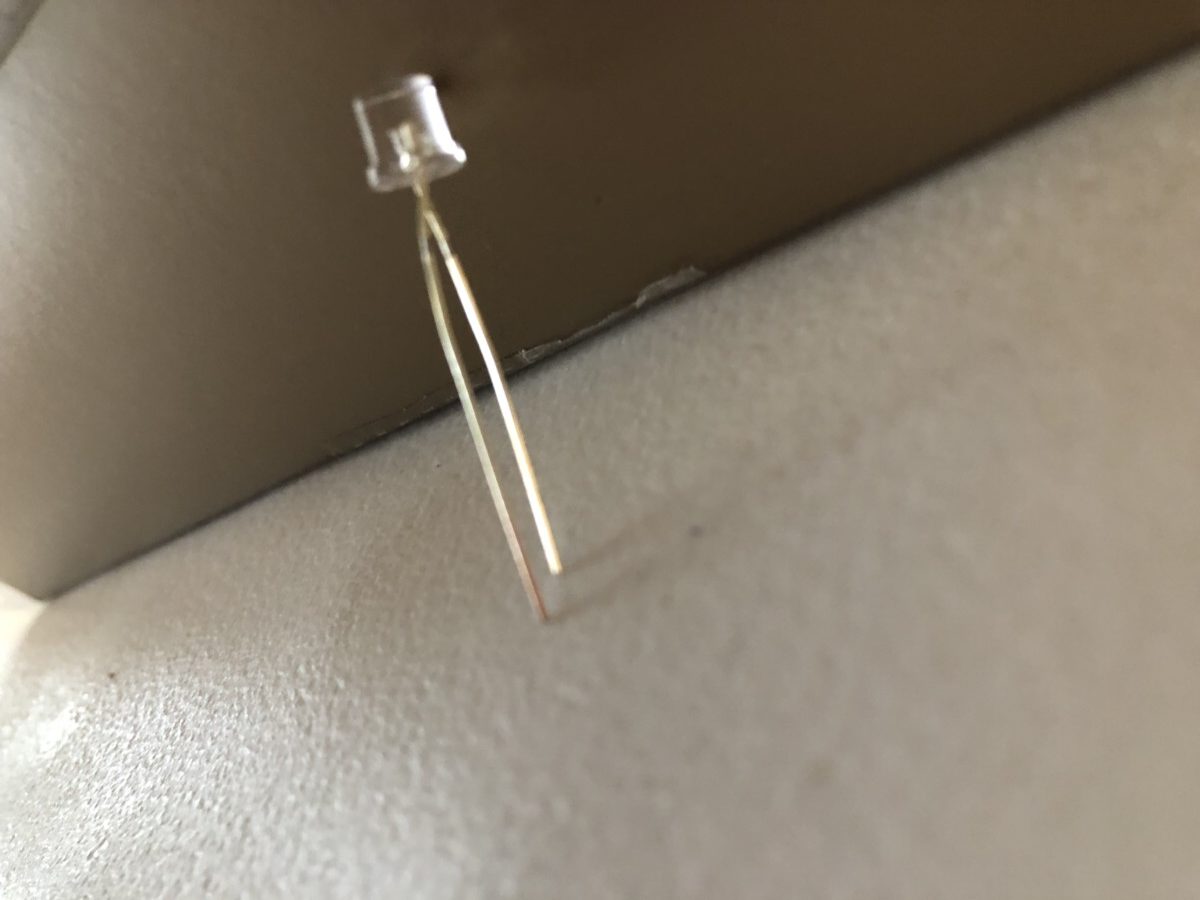
LED
An LED (or a light-emitting diode) can light up when you power it. There are many different colored ones like red, yellow, green, or blue.

Since an LED is a diode, it only works when a current flows through a specific way. That means if you insert it into your breadboard the wrong way, it won’t work!
Let’s break down the anatomy of an LED pin so you know how to insert it.
An LED has a long leg (also known as the positive leg) and a short leg (the negative leg). The long leg is called the anode and the short leg is the cathode. The current will flow into the anode and out the cathode, so you need to connect the anode to power and the cathode should be connected to the ground.
Pushbutton
Pushbuttons are very useful for Arduino projects and add another layer of complexity and functionality.
A pushbutton is basically a component that can connect two points on a breadboard and close a circuit. It allows a current to pass through and activate another component (like an LED) when pressed, but it restricts the flow of current when the button is not pressed.

You can think of a pushbutton as a common light switch. When you flick it up, a light turns on, but when you flick it down, the light turns off. Understandably, this is a poor analogy because you don’t need to press the pushbutton again to “turn it off”.
I’ve used this in my Spaceship Interface project (by Arduino). How it works is that the LEDs flashed from green to red whenever I push the button.
Potentiometer
A potentiometer, also known as a rotary angle sensor or a pot, has a turnable knob that changes the resistance. I see this as a more complex resistor since users can change the value.
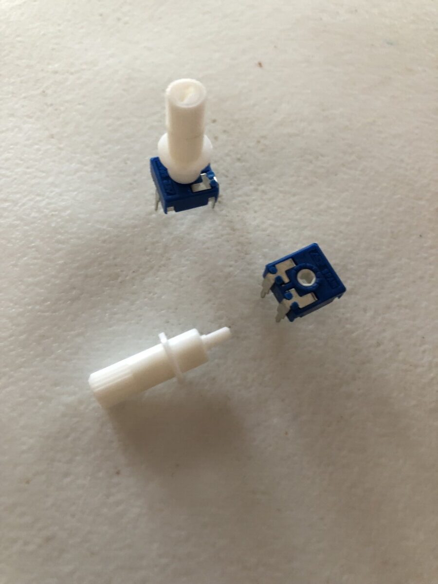
It only has 3 legs. 2 of the legs (which are next to each other) connect to a fixed resistor’s end. The third leg (which is by itself) calculates the voltage difference when you turn the knob.
A potentiometer used for Arduino can only turn 270 degrees and gives an analog input, which means it can hold more than 2 different types of value rather than 2 (like digital).
You can imagine it as a volume control knob on a radio or the knob on one of those really old TVs.
I’ve used a potentiometer in my Mood Cue project where I turned the pot’s knob to let people know how I was feeling.
Servo Motor
Similar to a DC (direct current) motor, the servo motor can rotate, but it is limited to 180 degrees and it’s a slower rotation compared to the DC motor. It has a shaft that changes position when the servo motor rotates it.
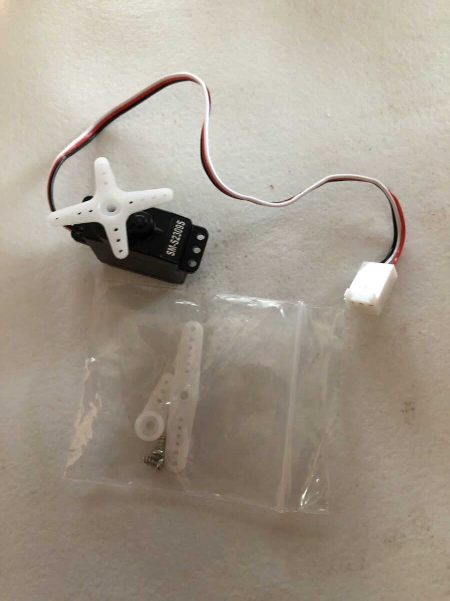
Your Arduino sends electric pulses to it, which tells the motor what position it should be in.
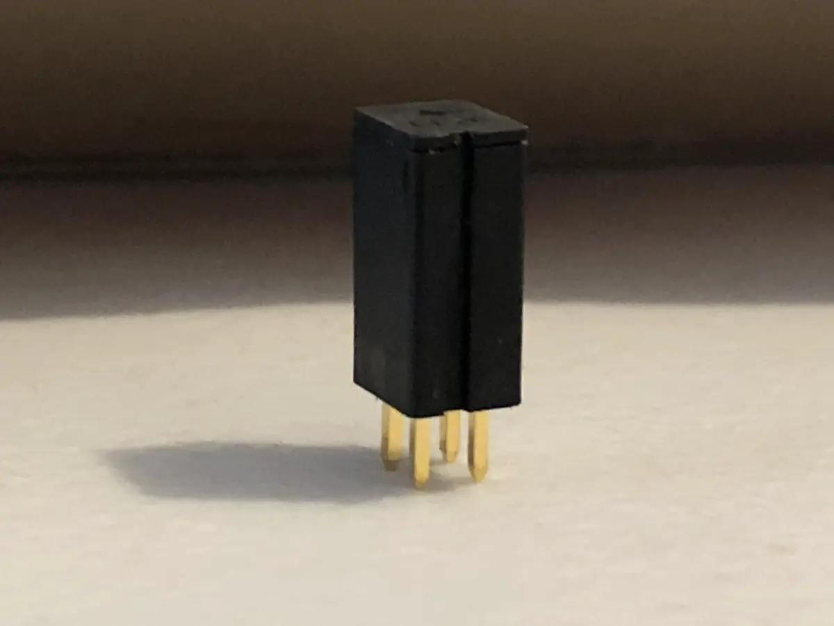
For connections, it has 3 female headers (which are just holes), which means you need male headers (which are actual metal pins) to connect it to the Arduino.
I’ve used a servomotor in my Knock Lock project where the servomotor would turn and “unlock” once I gave it the proper “password”.
Temperature Sensor
As the name suggests, a temperature sensor senses and measures the temperature. This sensor can only measure temperature as low as -58°F ( or -50°C) and as high as 257°F (or 125°C).
It’s a black component with three legs where the two outside legs connect to power and ground while the middle leg changes the voltage depending on the temperature (whether it’s hot or cool).
How it works is by changing its voltage output based on the temperature it senses in its surrounding environment.
Personally, I’ve used it to create a “fan”. Basically, when the temperature sensor sensed a temperature lower than 80 degrees, I had the DC motor spin and blow wind towards my face.
I’ve also used this sensor in my Love-O-Meter project, which determined my “love” for something based on my body temperature.
DC Motor
A DC motor (or a direct current motor) takes the electrical energy the Arduino sends it and changes it into mechanical energy. Direct current means that the electrical current only flows in one direction.
There are coils of wire inside the grey cylinder shell that become magnetized when a current flows through it. The shaft will spin when the magnetic field attracts and repels the magnets.
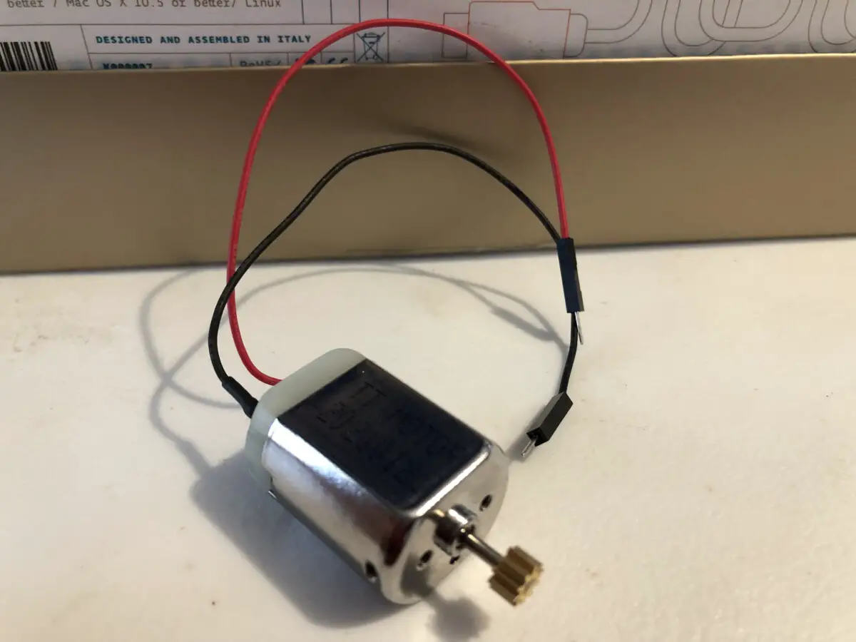
Since a DC motor uses more power than the Arduino can provide, you need a diode to regulate it and make sure it’s getting the right amount of voltage it needs to be powered. It also ensures that the voltage isn’t high enough to damage the transistor.
DC motors are great for projects such as the fan I mentioned, a Zoetrope, and a motorized pinwheel. You can find the last two projects’ instructions on the official Arduino Youtube channel or the Official Arduino Starter Kit book.
Phototransistor
As an analog device, the phototransistor can sense the levels of light in its surroundings and change the voltage accordingly to match it.
This component is similar to a LED pin because it has a short leg and a long leg. The short leg (also known as the cathode) is where the current flows out of to get to the ground while the long leg (the anode) receives the current.
Like a LED pin, the phototransistor is polarized, which means it must be placed in a specific way, or else it won’t work because the current can’t flow through it.
Phototransistors were great in my Color Mixing Lamp project because they could control the different light colors in my RGB LED based on the light they sensed.
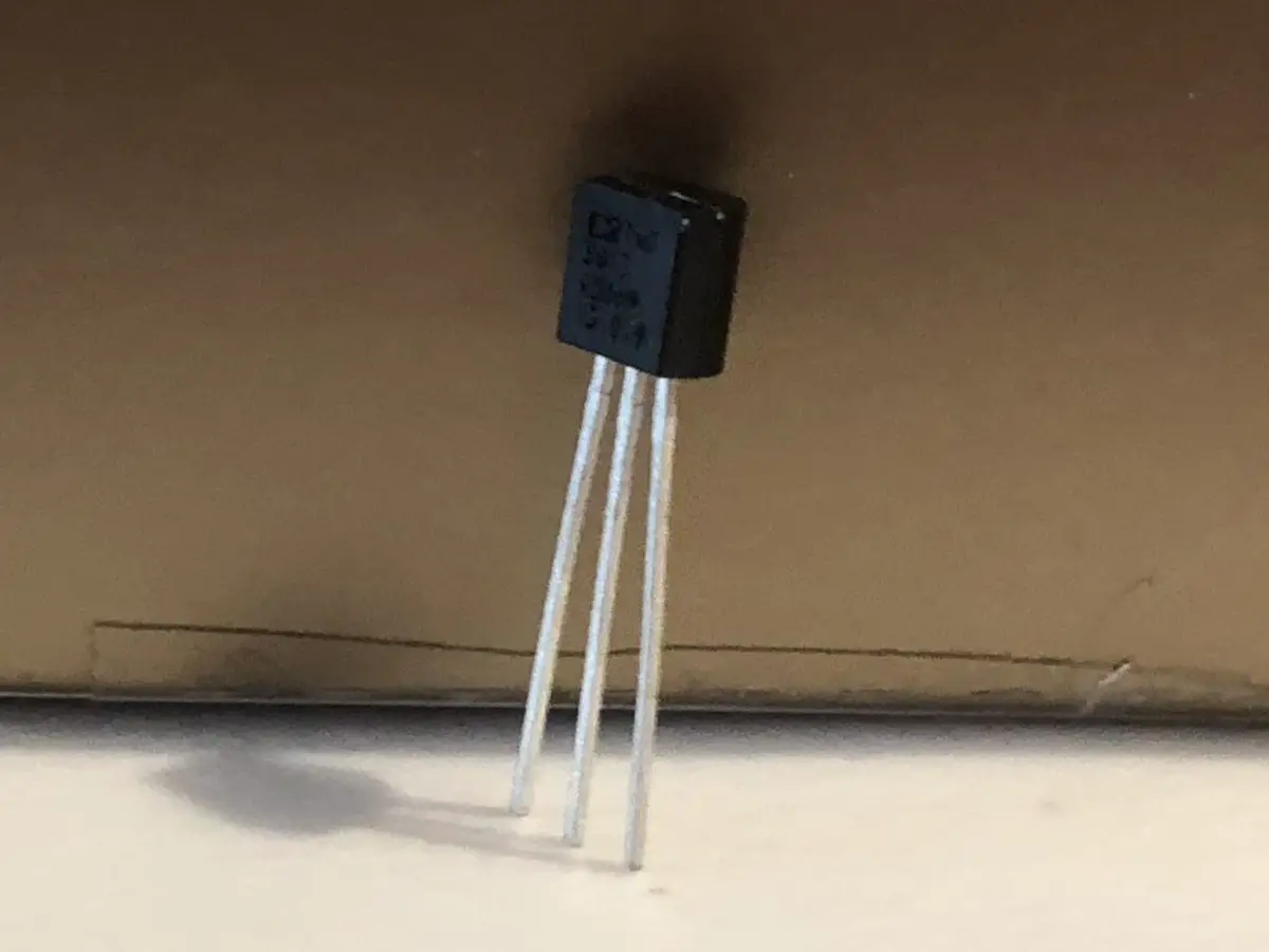
Transistor
Transistors are like electrical pushbuttons since it uses two states for its electrical switch: “on” or “off”. This component is great for controlling components that use high voltage (like a motor).
A transistor has 3 leads (or legs, which are the metal wires coming out of it).
The first leg connects the transistor to the ground, the second (or middle) one controls the voltage, and the third leg connects to the Arduino. The circuit between the ground and other components is closed when the Arduino receives a voltage from the third leg.
Transistors can get pretty hot, so there is a hole in the grey metal rectangle so that you can screw in a heat sink to cool it down.
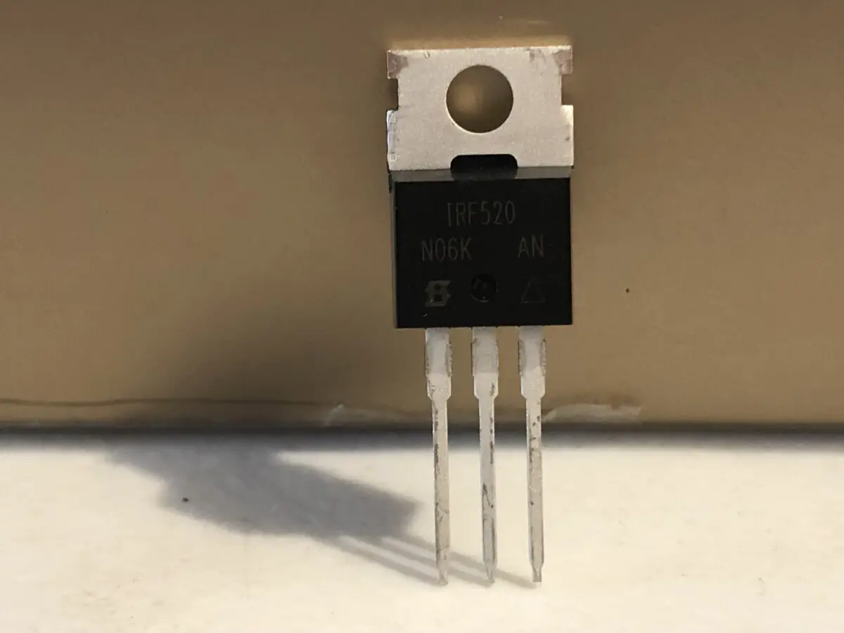
Diode
Just like a transistor, a diode is great for handling components with high voltage loads (like the motor). It makes sure that electricity only flows in one direction, and it’s polarized. This means that the direction you insert the diode into the breadboard matters.
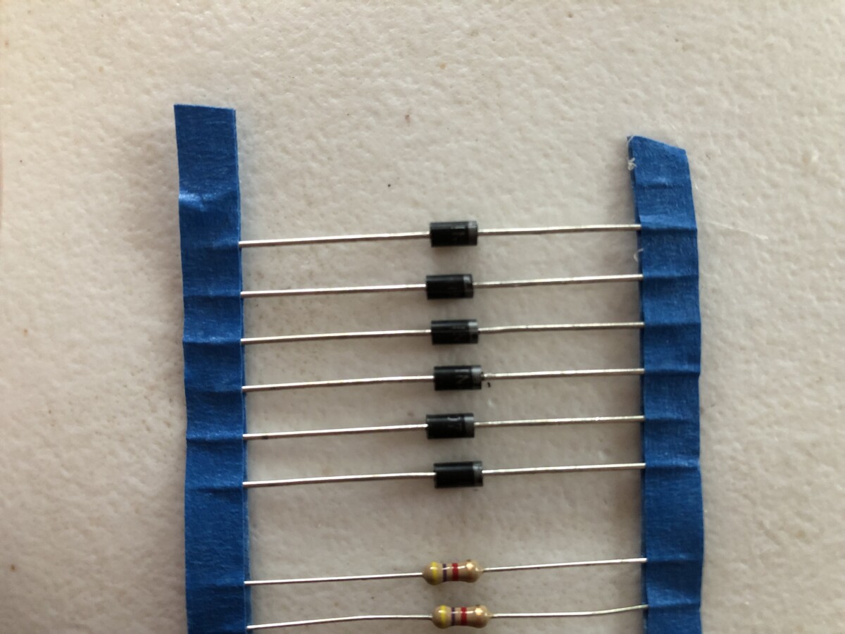
The placement matters because the diode can block the flow of current if it’s placed one way, and it can allow the current to pass through when placed the other way.
Similar to a LED pin, a diode has a cathode and an anode. Unlike the LED, one leg is not necessarily longer than the other. You can tell which leg is the cathode by looking at the band on the body of the component. The cathode is whichever leg the band is closest to.
As a refresher, the anode connects the circuit’s points of higher energy while the cathode connects to ground or the point of lowest energy in the circuit.
Tilt Sensor
A tilt sensor is a special kind of switch that either opens or closes depending on its position. This basically means that it can sense the tilt of the object.
It is a hollow cylinder with a metal ball that rolls around and makes a connection between the two leads when it’s tilted.
I’ve used it in my crystal ball project. This project mimicked a Magic 8 ball because I had to “shake” or tilt my Arduino and the breadboard to get a different response.
Piezo
A piezo is basically an electrical component that can detect noise and vibrations. It will create a voltage whenever it’s deformed by a sound or vibrations.
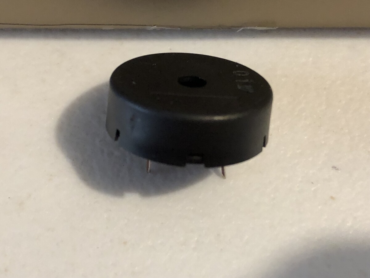
It is a small, circular black component that can also produce its own noise when you apply a voltage to it. This voltage causes the piezo to vibrate and create a tone. The noise it produces is a little annoying, but you can get used to it.
I’ve used this fun component in my knock-lock project. I had to rap my knuckles on the piezo a certain number of times to have the servomotor turn and “unlock” my box.
Summary – tl;dr (Too Long; Didn’t Read)
Here are the key takeaway points you should keep in mind after reading this article:
- The 15 equipment you’ll need (besides the Arduino) are:
- USB cable
- Breadboard
- LED pin
- Diode
- Phototransistor
- DC motor
- Resistors
- Temperature Sensor
- Tilt Sensor
- Piezo
- Transistor
- Servo motor
- Potentiometer
- Pushbutton
- Jumper wires
In the end, you should be well-equipped with all the equipment you’ll need to create some Arduino projects!