Arduino Pins Guide: Their Functions And How To Test Them
Arduino pins are very essential on the Arduino board. They can output varying levels of voltage, especially depending on the type of pins you use.
However, if you sense that your Arduino pins are not responding, this guide is for you. This is also for you if you don’t fully understand the purpose of Arduino pins.
This guide will first explain the different types of pins on the Arduino and their functionalities. After that, I will discuss how you can test them along with other potential questions you may have.
Now, let’s dive in!
What Are The Different Types Of Arduino Pins?
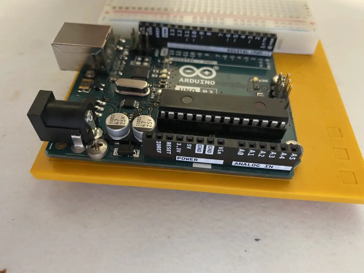
On the Arduino UNO R3 board, there are 3 different groups of pin headers: digital, analog, and power.
The pin headers are the black plastic holes that protrude outwards and are located along the edge of the board. Inside these holes, there are small metal clips that will latch onto leads (like the wire coming out of a resistor or LED).
This creates an electrical contact between the lead (of the component you are using) and the pin for the pin to function.
Digital Pins
The digital pin headers are numbered from 0 to 13 (which means there is a total of 14 pins). They are the longest black row on your Arduino board.
The digital pins serve two purposes: receiving input and sending outputs.
Digital means that there are only two states, just like a boolean has two states (true or false). As an input, the digital pins read only two different voltage states: low (0 volts) or high (5 volts). When they are purposed as an output, these digital pins send two different voltages: 0 volts or 5 volts.
If you take a closer look at the digital pins, you’ll notice there’s a squiggly line next to 6 of them. You should see it for pins 3, 5, 6, 9, 10, and 11. This symbol is meant to let you know that you can use these pins for pulse width modulation (PWM).
What is PWM?
Pulse width modulation is a method in which you can use your digital pins to create an illusion that they’re sending voltages in varying amounts.
For pins 0 and 1, you should notice the letters “RX” and “TX” next to them respectively. The “TX” stands for “transmit” and the “RX” stands for “receive”. These two pins allow your computer and Arduino board to communicate with each other.
TIP OF THE DAY!
Don’t use pins 0 and 1 if you can still use other pins. If you do, you might interfere with the serial communication between your board and computer.
Lastly, pin 13 plays another role: there is a LED on the Arduino that’s electrically connected to that pin. You can use it as an LED.
Analog Pins
There are a total of 6 pins that are labeled from A0 to A5 (where the A stands for analog).
Analog is different from digital because there can be many different states for the pins to be in instead of only 2.
The Arduino’s integrated circuit only recognizes digital states, so the Arduino’s Atmel microcontroller implements a technique called analog to digital converter (or ADC). In the integrated circuit, the pins utilize a chip that has the ADC built right in so that they can take the analog signals and convert them to digital signals.
Power Pins
There are a total of 7 pins under the power headers. The seven pins are the 3.3V pin, the 5.5 pins, the Vin pin, the reset pin, the IOREF pin, and the last two are both GND (ground) pins.
These pins are all used for powering the Arduino, except for the IOREF pin. That is the operating voltage reference, and you should never apply power to it at any time.
The 2 GND pins are for closing your electrical circuit and gives you access to 0V (the lowest voltage for the Arduino). There’s another GND pin on the digital header row (next to pin 13).
Having 3 GND pins is great because you can ground your circuits more than one way. Using more than one GND pin is great for the circuit because the resistance is reduced.
The 5V pin and 3.3V pin should be pretty obvious. The 5V pin provides 5V (volts) to your Arduino. This is useful if you choose to power your Arduino with a battery instead of a USB cable.
The 3.3 V pin provides 3.3V to your Arduino, which is useful for powering components and modules that only need 3.3V. Using this can save power and doesn’t overheat your Arduino board.
The reset pin does the same thing as pressing the reset button on your Arduino: it restarts the program you’re running to line 1. If you want to use it, just apply a low voltage.
If you want to learn efficient ways to reset your Arduino, check out my guide on resetting your Arduino. These 5 methods have been tested by me repeatedly.
Lastly, the Vin pin takes a voltage of 9V and serves as a power source besides the 5V. You’d use this instead of the 5V pin if your external power source supplies a voltage over 5V. Since your Arduino only uses 5V, the Vin pin will run the voltage (that is over 5V) through the voltage regulator to reduce it to 5V.
If you want to see how long an Arduino can run or how you can make your Arduino run for a long time, then you should go read my guide on how an Arduino can run 24/7. I talk about the 4 ways you can make it run constantly and factors you want to avoid that will diminish its ability.
Why Should You Test Arduino Pins?
You should test your Arduino’s pins to make sure it works properly. If it doesn’t work, then it would not follow your code correctly. This would make your project act sporadically and ruin the fun.
Without these pins, you lose a lot of functionalities since these pins also serve as inputs and outputs or power sources for your Arduino.
How To Test Your Arduino Pins
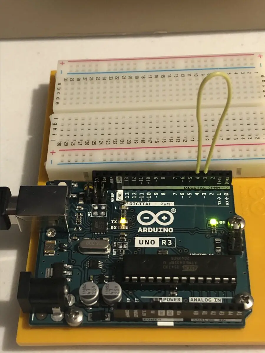
For this method, all you need to test your Arduino pins is the Arduino UNO R3 board, a single jumper wire (any color wire should work fine), a computer, and a USB cable.
For this test, we are setting one pin as an input and another pin as an output. The output pin would send 5 volts to the input pin. If the input pin receives it, that means that both the input pin and output pin are working properly.
The input pin will let you know it has received it in the serial monitor.
For this first example, we are testing pins 3 and 4.
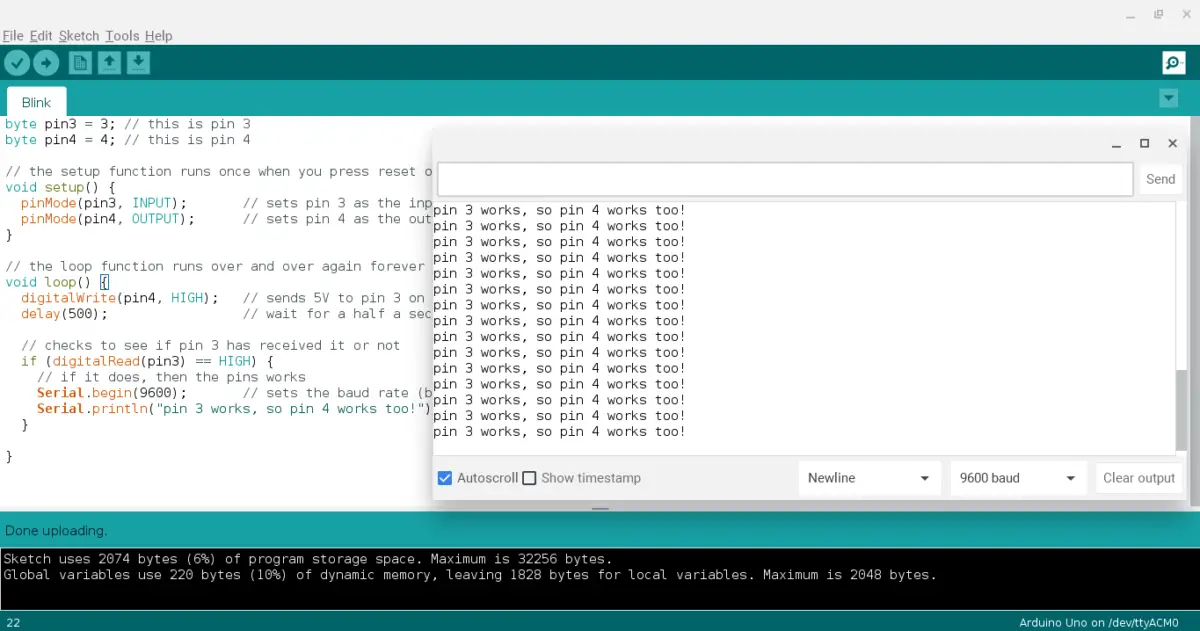
First, copy and paste the following code to your Arduino IDE (make sure to read the comments so that you understand what is happening).
byte pin3 = 3; // this is pin 3
byte pin4 = 4; // this is pin 4

// the setup function runs once when you press reset or power the board
void setup() {
  pinMode(pin3, INPUT);       // sets pin 3 as the input
  pinMode(pin4, OUTPUT);      // sets pin 4 as the output
}

// the loop function runs over and over again forever
void loop() {
  digitalWrite(pin4, HIGH);   // sends 5V to pin 3 on HIGH
  delay(500);                 // wait for a half a second
  // checks to see if pin 3 has received it or not
  if (digitalRead(pin3) == HIGH) {
    // if it does, then the pins works
    Serial.begin(9600);       // sets the baud rate (bits per second) or how fast information is transmitted between the serial monitor and Arduino
    Serial.println("pin 3 works, so pin 4 works too!"); // shows the message in the serial monitor
  }
}
Next, connect one end of a jumper wire to pin 3 on the Arduino and the other end to pin 4.
After that, connect your Arduino to your computer and upload the code.
Finally, go to your serial monitor (which is the magnifying glass icon located on the top right corner of your Arduino IDE) and check to see if the pins are working.
To test the rest of your pins, just connect the jumper to two different pins and rework the code to fit the pins you are testing.
Here’s some more code you can use when testing other pins:
//use the following code for testing pins 5 and 6

byte pin5 = 5; // this is pin 5
byte pin6 = 6; // this is pin 6

// the setup function runs once when you press reset or power the board
void setup() {
  pinMode(pin5, INPUT);       // sets pin 5 as the input
  pinMode(pin6, OUTPUT);      // sets pin 6 as the output
}

// the loop function runs over and over again forever
void loop() {
  digitalWrite(pin6, HIGH);   // sends 5V to pin 5 on HIGH
  delay(500);                 // wait for a half a second
  // checks to see if pin 5 has received it or not
  if (digitalRead(pin5) == HIGH) {
    // if it does, then the pins works
    Serial.begin(9600);       // sets the baud rate (bits per second) or how fast information is transmitted between the serial monitor and Arduino
    Serial.println("pin 5 works, so pin 6 works too!"); // shows the message in the serial monitor
  }
}
The following code will test pins 7 and 8:
byte pin7 = 7; // this is pin 7
byte pin8 = 8; // this is pin 8

// the setup function runs once when you press reset or power the board
void setup() {
  pinMode(pin7, INPUT);       // sets pin 7 as the input
  pinMode(pin8, OUTPUT);      // sets pin 8 as the output
}

// the loop function runs over and over again forever
void loop() {
  digitalWrite(pin8, HIGH);   // sends 7V to pin 7 on HIGH
  delay(700);                 // wait for a half a second
  // checks to see if pin 7 has received it or not
  if (digitalRead(pin7) == HIGH) {
    // if it does, then the pins works
    Serial.begin(9800);       // sets the baud rate (bits per second) or how fast information is transmitted between the serial monitor and Arduino
    Serial.println("pin 7 works, so pin 8 works too!"); // shows the message in the serial monitor
  }
}
The following code will test pins 9 and 10:
byte pin9 = 9; // this is pin 9
byte pin10 = 10; // this is pin 10

// the setup function runs once when you press reset or power the board
void setup() {
  pinMode(pin9, INPUT);       // sets pin 9 as the input
  pinMode(pin10, OUTPUT);      // sets pin 10 as the output
}

// the loop function runs over and over again forever
void loop() {
  digitalWrite(pin10, HIGH);   // sends 9V to pin 9 on HIGH
  delay(900);                 // wait for a half a second
  // checks to see if pin 9 has received it or not
  if (digitalRead(pin9) == HIGH) {
    // if it does, then the pins works
    Serial.begin(91000);       // sets the baud rate (bits per second) or how fast information is transmitted between the serial monitor and Arduino
    Serial.println("pin 9 works, so pin 10 works too!"); // shows the message in the serial monitor
  }
}
The following code will test pins 11 and 12:
byte pin11 = 11; // this is pin 11
byte pin12 = 12; // this is pin 12

// the setup function runs once when you press reset or power the board
void setup() {
  pinMode(pin11, INPUT);       // sets pin 11 as the input
  pinMode(pin12, OUTPUT);      // sets pin 12 as the output
}

// the loop function runs over and over again forever
void loop() {
  digitalWrite(pin12, HIGH);   // sends 11V to pin 11 on HIGH
  delay(1120);                 // wait for a half a second
  // checks to see if pin 11 has received it or not
  if (digitalRead(pin11) == HIGH) {
    // if it does, then the pins works
    Serial.begin(111200);       // sets the baud rate (bits per second) or how fast information is transmitted between the serial monitor and Arduino
    Serial.println("pin 11 works, so pin 12 works too!"); // shows the message in the serial monitor
  }
}
The following code will test pins 12 and 13:
byte pin13 = 13; // this is pin 13
byte pin12 = 12; // this is pin 12
// the setup function runs once when you press reset or power the board
void setup() {
pinMode(pin13, INPUT); // sets pin 13 as the input
pinMode(pin12, OUTPUT); // sets pin 12 as the output
}
// the loop function runs over and over again forever
void loop() {
digitalWrite(pin12, HIGH); // sends 13V to pin 13 on HIGH
delay(1320); // wait for a half a second
// checks to see if pin 13 has received it or not
if (digitalRead(pin13) == HIGH) {
// if it does, then the pins works
Serial.begin(131200); // sets the baud rate (bits per second) or how fast information is transmitted between the serial monitor and Arduino
Serial.println("pin 13 works, so pin 12 works too!"); // shows the message in the serial monitor
}
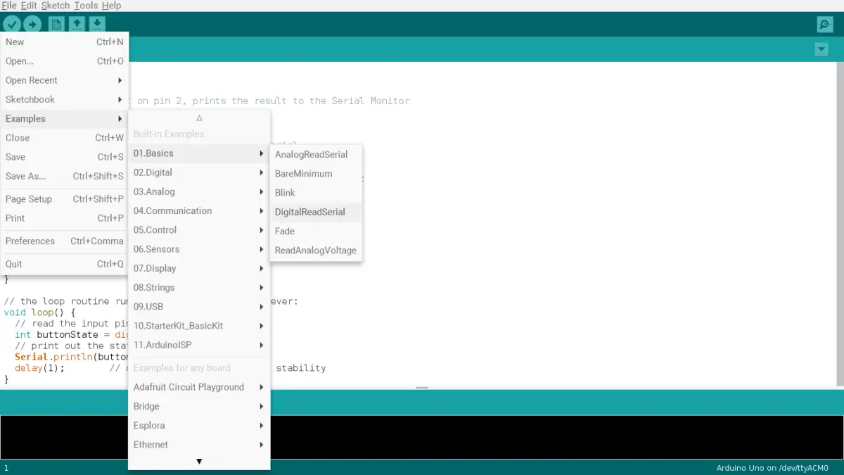
}If you want other methods for testing your digital and analog pins do the following:
- Go to your Arduino IDE and click Files > Examples > 01. Basics > DigitalReadSerial
- This will test the digital pins. Read the comments carefully to see how you can implement it.
- Go to your Arduino IDE and click Files > Examples > 01. Basics > ReadAnalogVoltage
- This will test the analog pins. Like before, read the comments to see how to implement it.
How Can Arduino Pins Be Damaged?
Arduino board pins can be easily damaged if you apply too much or too little current or voltage to them. Using a faulty chip or damaged board and electrostatic discharge are a few other reasons why your Arduino pins may not be functioning.
For example, if you are using an LED without a resistor, the LED will burn out in a few seconds and the pins may also be damaged. On the other end of the spectrum, the pins won’t work if you don’t supply enough voltage to the power pins.
To avoid or resolve these issues, I’d suggest the following:
- Make sure that your code is correct. Most of the time, people make a logical error that makes it seem that the pins are not working.
- Try figuring out the specifications for powering your Arduino. Don’t exceed the maximum voltage and make sure to apply enough voltage over its minimum.
- For instance, apply a voltage over between 7 to 12 volts to the Vin pin (if you’re using that as a power source) or 5 volts to the USB port.
- Change your chip if there are clear signs that the chip is not working.
- If all the previous options are not working for you, I’d suggest you buy a new Arduino board.
A new Arduino board is relatively cheap. For instance, an Arduino UNO R3 only costs $22. It will be a worthwhile investment since you won’t have to waste time and effort into finding and fixing the problem.
Summary – tl;dr (Too Long; Didn’t Read)
Here are the key takeaway points you should keep in mind after reading this article:
- Arduino has three main groups of pins: digital, power, and analog
- Digital pins can only read and output two voltages: 5V and 0V
- Analog ones can have varying amounts of voltages
- Power pins are meant for powering your Arduino
- Since most Arduino projects will rely on these pins, it is necessary for you to test them
- You can test your pins by using a jumper wire to connect the two pins on your Arduino board that you want to test and inputting the following code:
byte pin3 = 3; // this is pin 3
byte pin4 = 4; // this is pin 4

// you can modify the code to your choosing

// the setup function runs once when you press reset or power the board
void setup() {
  pinMode(pin3, INPUT);       // sets pin 3 as the input
  pinMode(pin4, OUTPUT);      // sets pin 4 as the output
}

// the loop function runs over and over again forever
void loop() {
  digitalWrite(pin4, HIGH);   // sends 5V to pin 3 on HIGH
  delay(500);                 // wait for a half a second
  // checks to see if pin 3 has received it or not
  if (digitalRead(pin3) == HIGH) {
    // if it does, then the pins works
    Serial.begin(9600);       // sets the baud rate (bits per second) or how fast information is transmitted between the serial monitor and Arduino
    Serial.println("pin 3 works, so pin 4 works too!"); // shows the message in the serial monitor
  }
}
In the end, I hope this article put a positive s-pin on your Arduino pin issues.